|
|
||
|
MST_K07_CL - SPEED REGULATOR FOR UNIVERSAL MOTORS WITH TORQUE CONTROL |
||
|
||
|
1 >>>
|
||
|
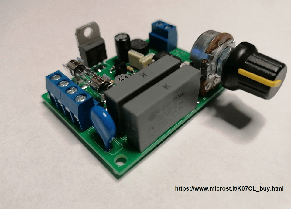
INTRODUCTION The MST_K07_CL is a regulator for universal motors (brushes) at 220V that allows to control the torque or to keep the rotation speed constant at the fixed value as the load varies. It is designed to work with washing machine motors equipped with a tachometer (or speed) sensor such as the MCA 30/64 motor. Figure 1 shows the photo of the controller assembled in the PCB version.
Fig. 1 - MST_K07_CL assembled DESCRIPTION OF THE REGULATOR The
MST_K07_CL regulator is the version with automatic torque control of
the MST_K07 universal motor regulator: the motor is adjusted so that
the rotation speed remains constant at the set value as the load
varies. If the load applied to the motor tends to reduce / increase the
rpm then the regulator will react by bringing the rpm value back to the
set one. This type of regulation is obtained through the closed loop
control that the regulator implements on the motor. This control is
based on the electrical signal coming from the speed sensor which
converts the rotation of the motor shaft into a proportional electrical
voltage. As a reference we take washing machine motors (such as the MCA
30/64) in which there is a tachometer sensor, coaxial to the motor,
which supplies an alternating voltage of amplitude proportional to the
rotation speed of the motor shaft. The MST_K07_CL regulator, suitable
for these types of motor, reads this voltage and compares it with a
voltage, set via a potentiometer, which represents the setting of the
rotation speed value to be adjusted. The regulator will then power the
motor so that the voltage value coming from the sensor, suitably
conditioned, remains equal to the voltage value set by the
potentiometer. To do this, the MST_K07_CL regulator uses an 8-bit
microcontroller, in which a firmware is loaded that implements a
digital PID regulator. The digital PID controllers then compare the
digital signals that represent the inputs (reference and feedback) and
generate an output signal which is the input of the power actuator.
Specifically, the actuator stage consists of the TRIAC piloted with the
ignition angle variation technique. In general, a TRIAC at the zero
crossing of the voltage present at its A1 and A2 anodes switches off
and on again when a current pulse is present on the GATE terminal. By
changing the instant of time in which the pulse is given on the GATE
terminal with respect to the previous zero crossing (it is said that
the phase angle is changed) the average voltage that powers the load is
varied as only a portion of the half-wave of voltage is supplied to the
load. So if you choose a zero ignition time (0 °) the whole half-wave
goes to the load and in this case you have the maximum power supply and
therefore the maximum motor speed. If you choose a time equal to half
of the half wave (90 °) only half of the sine wave will go to the load
and you have a 50% adjustment. Finally, if the TRIAC is turned on a few
moments before the next zero crossing (180 °), no voltage will go to
the load and there is a regulation of 0%. |
||
|
1 >>> |
||
|
|